
In figure 1.2b, we are matching R to Z o, so we place in a module which help us to match the impedances between R and Z o. We then introduce some device in between that will make R1 appear like R2 when seen from left side and R2 to appear like R1, when seen from the right side, so from both side it will appear that they are matched to the load and there is maximum power transfer. If they are connected directly there will be a mismatch and no maximum power transfer from R1 to R2.

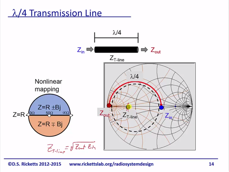
Which are to be matched, i.e R1 not equal R2. In figure 1.2a we have two different resistance R1 and R2 Let’s discuss various method by which different impedances can be matched to the characteristic impedance. At the input (left most side), we should see a characteristic impedance Z o and the module should be completely lossless (ideal) to allow maximum power transfer to load(Z). Let’s start with the first example which has a matching unit (transformer) which can convert the output (Z) impedance to the characteristic impedance Z o, which is shown in figure 1.1. This module is known as a matching unit or matching transformer. We then need a module or device which will transform this impedance to the characteristic impedance. But as we have seen, this matching condition is not always feasible. When impedance is equal to characteristic impedance (Z o), there is no reflection on the line, hence there is maximum power transfer. In this article we are going to learn about the most important application of Transmission Lines, which is “Impedance Matching”. From previous article, i have dealt on transmission lines.


 0 kommentar(er)
